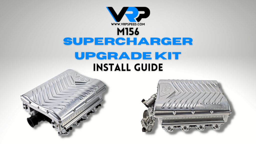
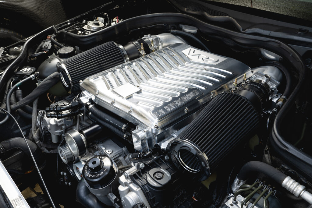
VRP M156 3.0L Supercharger Install Guide
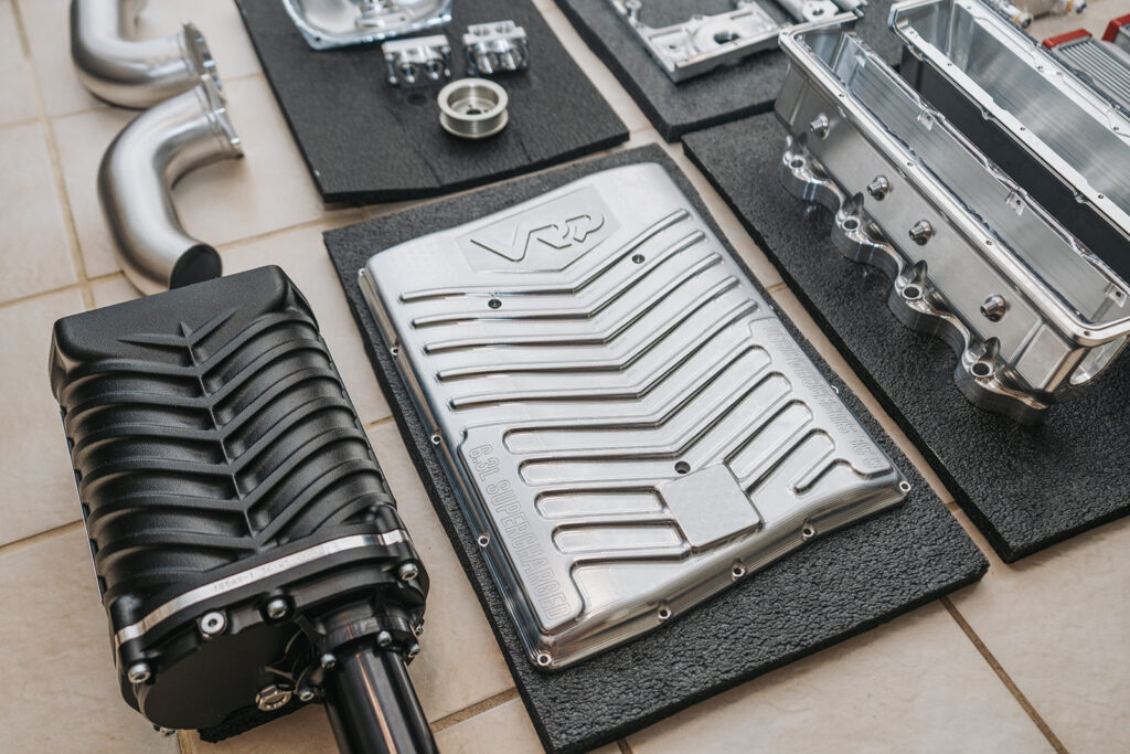
Part 1: Lower Manifold
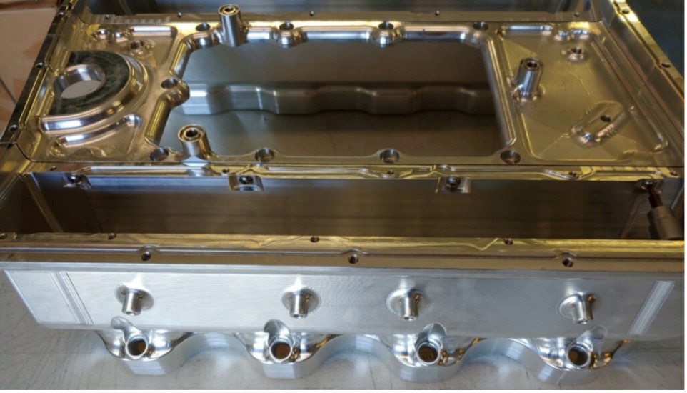
To start, we are going to assemble the lower manifold.
You will need the center plate and both the left and right runner.
Step 1:
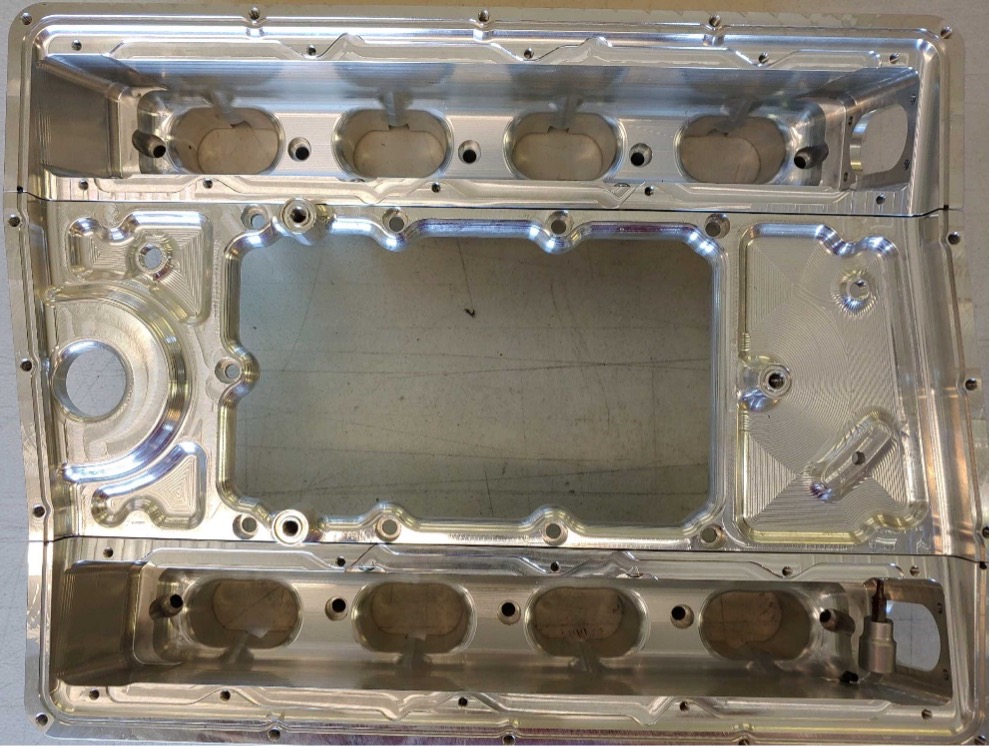
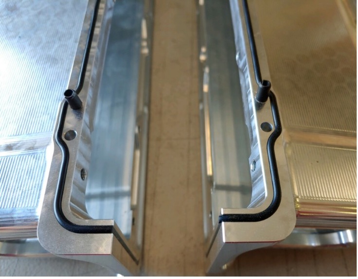
Cut the o-ring material to length and insert into the inside slot on the left and right manifolds (approximately 21” or sp146) and tap in 4x dowels sp164
Step 2:
Assemble the lower half of the manifold connecting the runners to the center plate using the 8x M6 button head bolts with 3mm hex head socket (sp150)
Step 3:
Install the bypass valve onto the center section using 3x M6 bolts, and install Gasket material sp146 (approximately 31 inches)
Part 2: Supercharger Unit and Inlet
Next, we are going to assemble the supercharger unit and inlet
Step 1:
Install o-ring gasket material into snout (sp161)
Step 2:
Install the Snout onto the Supercharger using 4x M8 bolts with 6mm head (sp142)
Step 3:
Install the Supercharger pulley using 4x M6 bolts with 5mm hex heads (sp130)
Step 4:
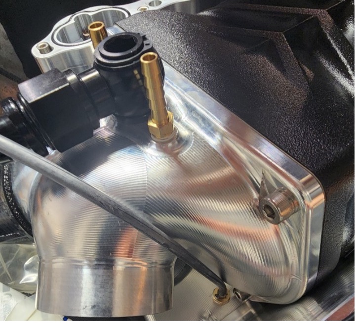
Install the banjo fitting, and both of the 3/8 barbs into the unit (The newest revision has 1 bottom port and one rear port on the snout, Install one barb fitting onto each)
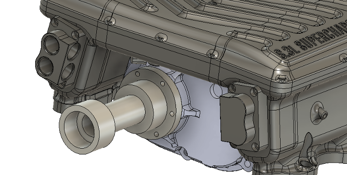
Part 3: Combine Supercharger and Lower Manifold
First, fill the supercharger to the center of the viewer with Supercharger oil and remove any tape from the unit
Then, place the Supercharger on the table with the rotor opening upwards
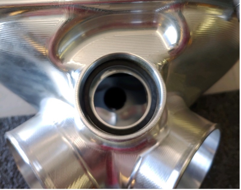
Insert the flat o-ring into the bypass valve slot on the snout (sp162)
With Gasket material in, place bolt the lower manifold to the supercharger using 9x M10 bolts.
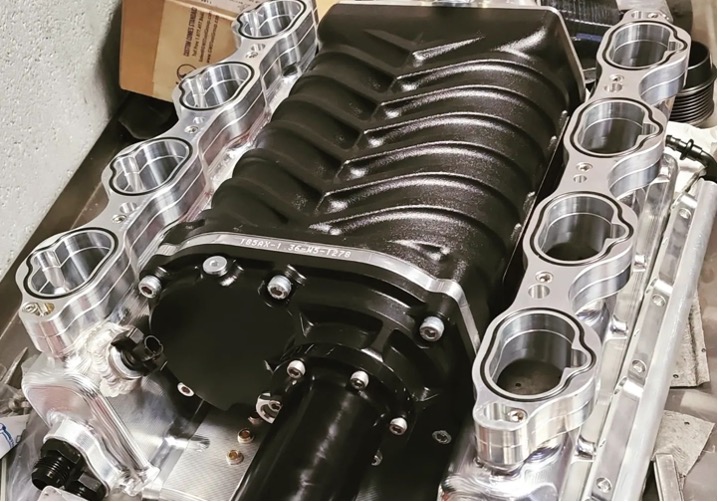
Install the o-rings into the slots on the runners for the intake ports.
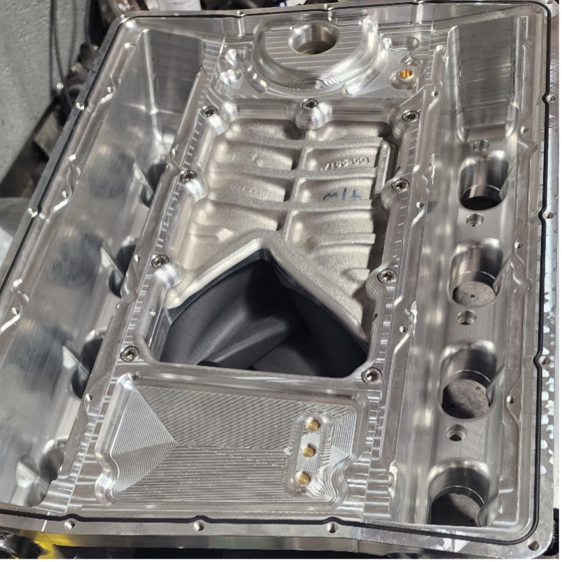
- Cut and insert gasket material into the top slot on the lower manifold. Use A Dab of RTV where the ends of the oring material meets. (see picture from 4.) (sp146, aprox 65”)
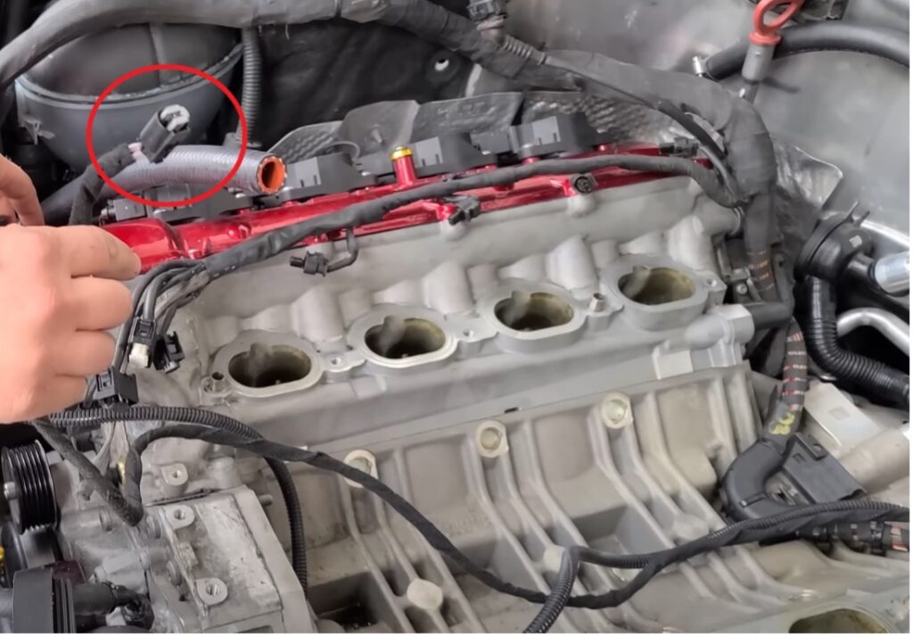
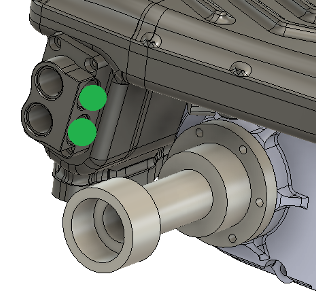
- Remove your factory IAT sensor from the rear of your facrory intake manifold and install into the drivers side of the unit (Shown above infront of the supercharger on the left side of the image)
- Remove your factory MAP sensor from the front of your factory intake manifold and install in the center plate of the main unit, (above the supercharger drive snout)
- Install 2x 3” couplers to the rear inlets of the snout, Make sure the ends of the clamps are rotated so that the screws will point straight back to the firewall when installed.
Part 4: Fuel System
Flip the assembled supercharger unit right side up. The next steps will be easier if you hang the back of the unit off the end of a workbench.
- Insert the 14mm injector spacers into the fuel rail
- Screw the 4 black ORB to an fittings into each end of the fuel rails
- Install your fuel injectors to the rails
- Attach the fuel rails to the sides of the unit. The rail with the fuel pressure sensor port goes on the drivers side.
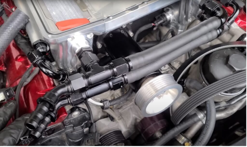
Next you will assemble Push Lock Fuel lines using the Aeroquip line and fittings provided
The image below shows how to assemble the rear section of the fuel lines.
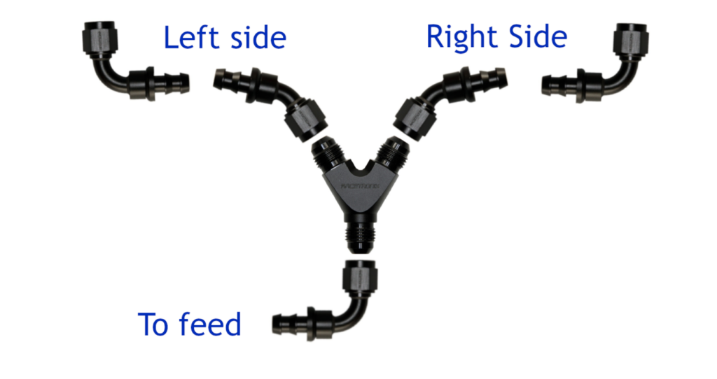
- Screw the 90* fittings to the rear fuel rails and connect the 2 45* fittings to the Y, Holding the Y in the center of the Inlet measure for your lines.
- Cut 2 lengths of push lock line to fit the first 2 sections.
- The final section of the rear line cannot be measured until the unit is installed in the car, it will connect directly to the factory fuel feed
The front line is very simple, The front line uses 2 90* fittings, and the push lock line. You want the front line to loop under the drive snout and leave some slack. (Your line will be blue)
Measure, cut, and assemble this line now, but leave it off of the unit, as it will be in the way for the coolant manifold installation. (to double check your length before you cut you can put the coolant manifolds into place and make sure the line will clear them)
Part 5: Final Assembly Steps
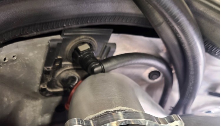
Under the snout there are 2 connections, (One connection was moved to the rear of the snout between the intake tubes)
- Banjo fitting – This will connect to the PCV valve connect a vacuum line to this banjo, You will cut it to the length of your catch can location, leave it long for now.
- The first 3/8 fitting goes to evap
- The second 3/8 fitting goes to the brake booster, you will use the plastic GM connector for that connection on the firewall.
The ports in the front of the unit are there for you to run boost references or whatever you may need them for. These simply get plugged with the provided 1/8npt plugs.
Prior to placing the unit onto the engine, put 2 more T clamps on the silicone couplers, with the nuts pointing straight up, It will be very difficult to get them back there once its in the engine bay.
Part 6: Pre Vehicle Assembly
Prior to moving forward:
- Remove the factory Intake manifold
- Remove factory power steering reservoir, (Disconnect the lines at the reservoir)
- Remove the Lift Bracket and Engine cover Holding bracket
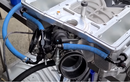
Rotate the rear breather tube 90* to clear the supercharger it is highly recommended that you use a Catch can setup for your breather connection
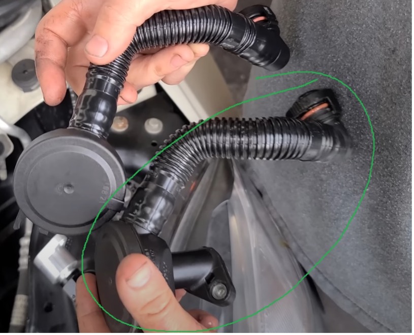
Install the PCV Valve to the engine block as shown, (VRP catch can fitting shown) if using a catch can you can run this catch can line now keeping it against the firewall.
On the passenger side remove the hard plastic cover from the wiring harness above the intake ports on the head.
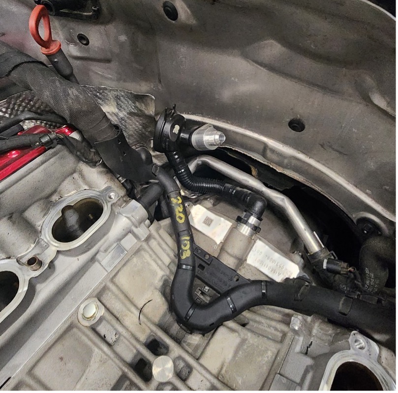
Remove the engine hoist bracket behind the valve cover on the driver’s side and cut the evap line as shown
Locate the factory IAT sensor wire by the drivers side valve cover, Cut and Extend the wires 24”(The new IAT sensor is located on the front inside of the drivers runner, you will run the line under the unit
Part 7: Installing Into Vehicle
- With assistance, set the supercharger onto the engine
- Take note of what direction the injector connectors are pointing.
- You MUST attempt to plugin the injectors BEFORE you bolt it down, otherwise you may have to undo everything past this step to rotate the injectors to clear the valve covers.
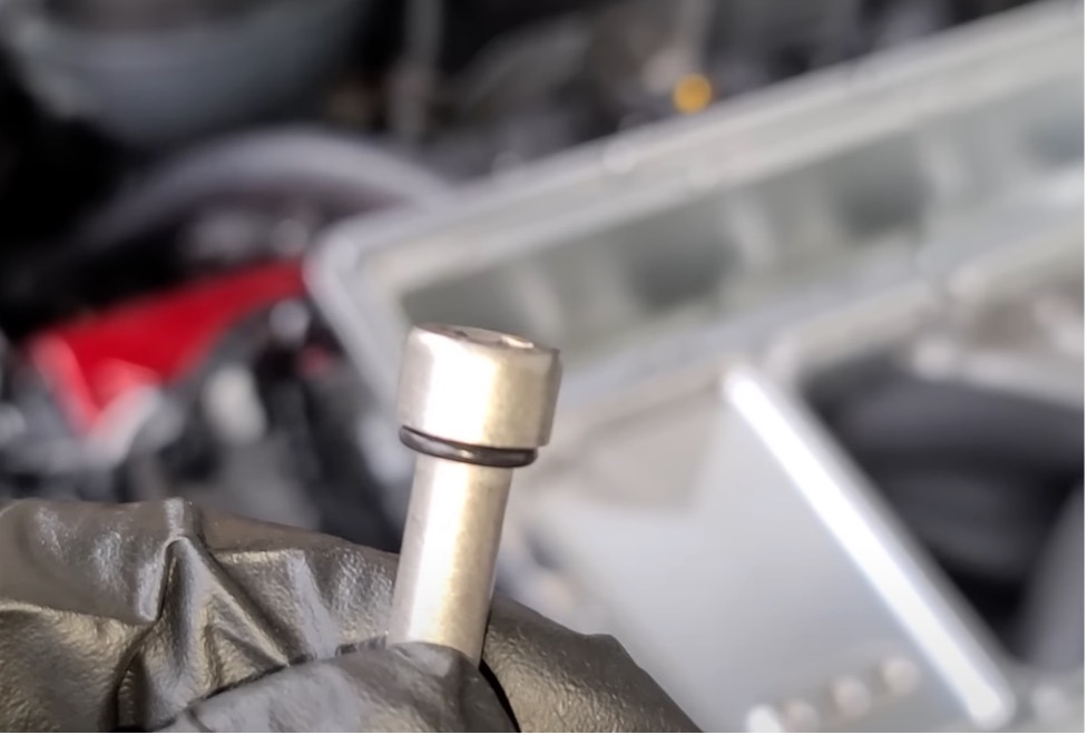
Use 10x sp155 with 6mm hex to install the supercharger to the engine. Add an o-ring to each
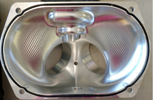
With the orange gaskets on the ends insert the intercoolers into the runners
Install the 4x Intercooler brackets to secure the intercoolers into the runners using 12x sp149 with 3mm hex
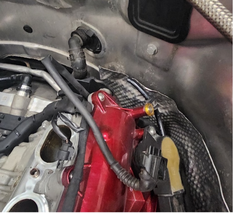
- Cut to length and connect the Vaccuum line from the banjo fitting to your factory PCV.
- Using the GM fitting for reference, pull a 3/8 line from one of the brass fittings to the Brake booster connection, Cut and connect.
Connect the final 3/8 line to the EVAP hose on the drivers side valve cover.
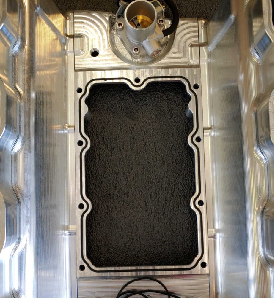
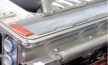
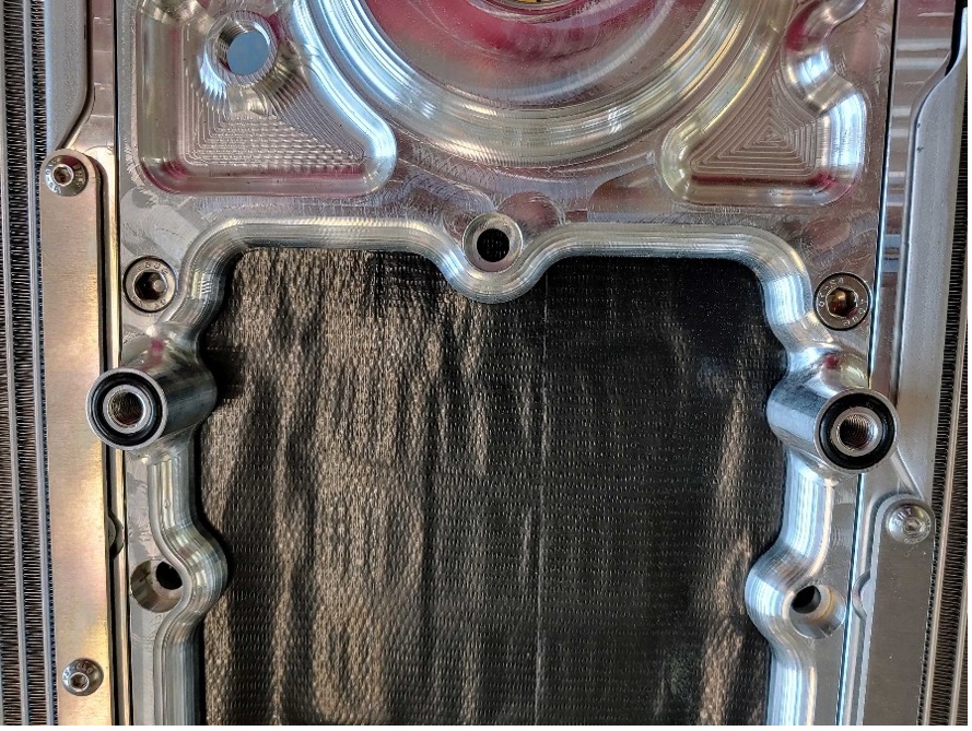
Install the Lid.
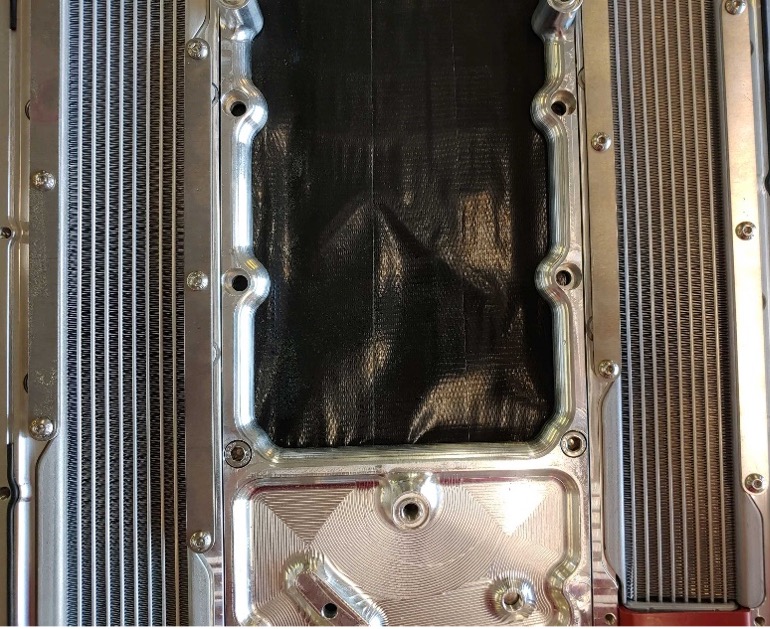
Place 3 orings into the center stands at the top and bottom of the supercharger opening.
Inspect the gasket installed previously to make sure it is still in place
- Put the lid into place and secure using the button head bolts provided
- 2x sp155 for middle rear
- 1x sp154 for center
- 16x sp151 around lid.
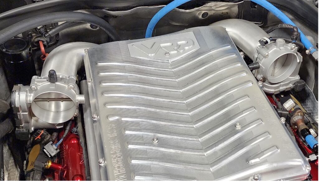
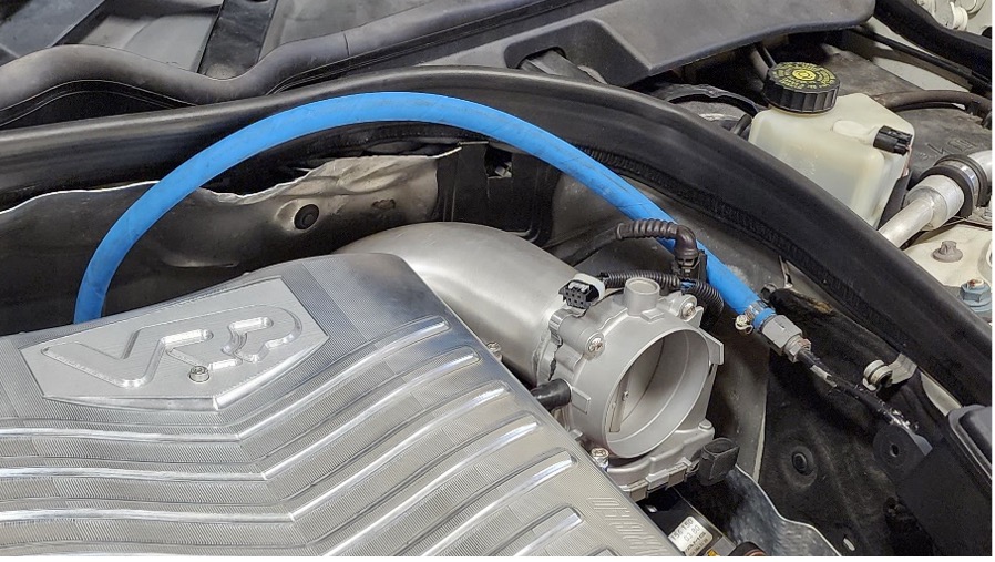
Throttle Body Pipes
- With the tube ends first, Slide the Intake Tubes behind the supercharger into the couplers and tighten the clamps down to hold the pipes in place, don’t fully tighten yet.
- Install the throttle bodies to the ends of the pipes using 8x m6 bolts
- Remove the factory Throttlebody harness from your factory intake manifold. Extend the short side of the harness approximately 10” to reach the passenger side throttlebody.
Tighten the clamps down with the throttle bodies in position resting on the valve covers
Cooling Lines:
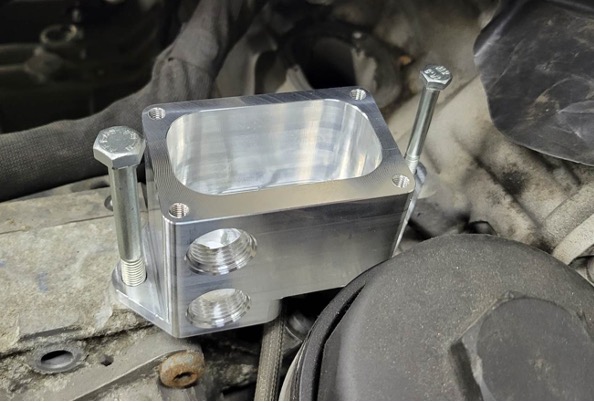
**The coolant lines have been updated since this guide was made, The photos will not directly represent the fittings used as the manfold blocks now eliminate 90* fittings and T fittings
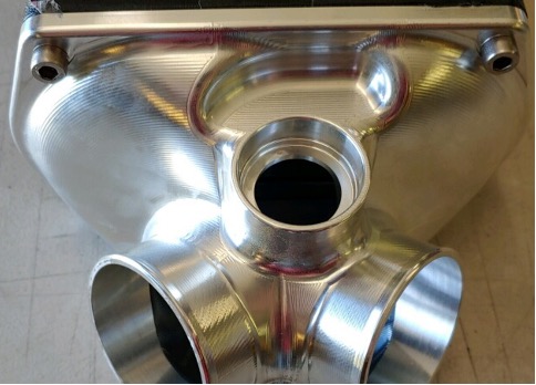
- Install the oring gaskets to the front of the lower manifold where the coolant manifolds attach
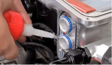
Apply lubricant to the blue orings on the intercoolers
As this Image demonstrates, The passenger side manifold has 4 outlets, while the passenger side unit has 2.
- Install both coolant manfolds
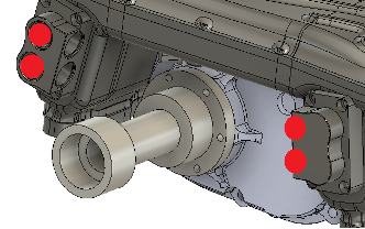
- Install the 10 orb to -10an straight fittings on the locations shown in red
Install the 10orb to Barb fittings in the locations shown in green (passenger side)
- Connect the Barb Fittings to the Drivers side -10an straight fittings using the Barb to -10an adaptor fittings and the hose provided.
- 2x 45* -10an fittings will attach to the passenger side -10an straight fittings, These should point town towards the front passenger side of the vehicle,
These coolant connections replace the version 1 setup shown here.
Connect the 2x 24* connections to your coolant circuit. Please refer to the diagram for hose routing
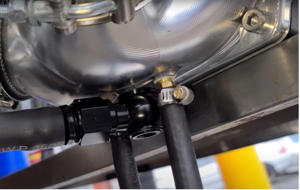
Fuel
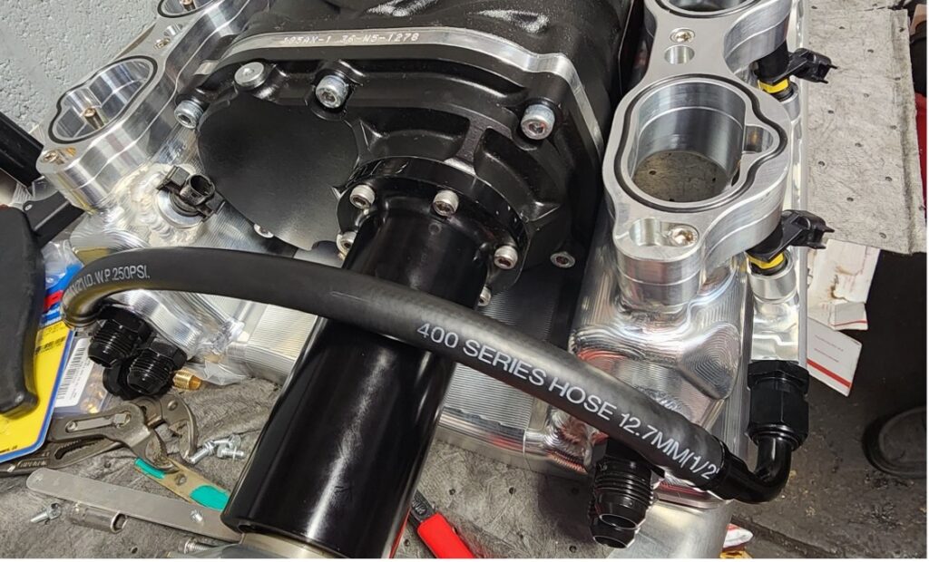
Now that the coolant lines are in place, Connect your front fuel line loop under the supercharger drive snout
Run the remaining feed line from the back of the supercharger to the factory feed, Connect the barb adaptor fitting to the rail
Cut to length and connect the feed line
Power Steering
**This power steering solution was created post production please refer to the image below for mounting location,
Use the provided 5/8 and ½ fittings to connect your factory lines to the reservoir
Use your factory power steering lid with this setup.
Intake
- Install the 2x 3.5” black silicone couplers to throttlebodys
- Remove the Maf sensors from your factory Intake boxes using a small flat head screwdriver, pry the metal clip off of the flat side of the sensor. Install the Maf sensors into the 3d printed Maf adaptors reusing the metal clips from the factory intake.
- Install the Maf adaptors to the throttlebody and plug in using the MAF sensor extension harnesses.
- Install your desired intake setup to the Maf adaptors minimum of 3” piping recommended.
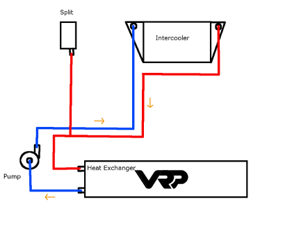
Heat Exchanger and Cooling
- Remove the front bumper and install the Heat exchanger to the bottom of the crash bar using 4x self-tapping bolts
- Attach the split cooling reservoir to the Radiator support bracket.
- Block off the small return on the bottom of the split cooling tank.
- Install the Intercooler pump in a secure location and wire the pump to a switched power source
- Run the rest of the system according to the diagram below
Tuning
If using a VRP tune with this kit Please refer to the instruction packet included with the handheld. If you need a tune you can find it here: https://www.vrpspeed.com/product/vrp-m156-supercharged-tune/